Part I: Introduction and Foundational Principles
Context, legal basis, and fundamental principles of TCVN 9362:2012, ensuring users understand the standard’s role and the indispensable prerequisites for its application.
Chapter 1: Role and Importance of TCVN 9362:2012 in Vietnam’s Construction Industry
1.1. Official Name and Legal Status
National Standard TCVN 9362:2012, fully named “Specifications for design of foundation for buildings and structures”, is the core technical document regulating foundation design work in Vietnam. Its legal status is established through a rigorous issuance process: compiled by the Institute for Building Science and Technology (under the Ministry of Construction), proposed by the Ministry of Construction, appraised by the Directorate for Standards, Metrology and Quality, and finally announced by the Ministry of Science and Technology. This process confirms TCVN 9362:2012 as a legally binding regulation, serving as the basis for engineers and contractors to perform design, appraisal, and acceptance, ensuring quality and safety for construction projects.
1.2. Historical Context: From TCXD 45:1978 to TCVN 9362:2012
TCVN 9362:2012 is not an entirely new standard but the result of converting the old industry standard TCXD 45:1978, according to the Law on Standards and Technical Regulations. A deeper look into its origins reveals that TCXD 45:1978 was essentially a translation of the Soviet standard СНиП II-15-74, issued in 1974, with some adjustments to remove foundation issues uncommon in Vietnam.
This origin is not just a historical detail but a determining factor affecting the standard’s structure, methodology, and even the challenges faced in its application today. Soviet technical standards from the pre-personal computer era were developed with a philosophy suited for manual calculations. This led to a prescriptive, step-by-step structure heavily reliant on pre-calculated lookup tables to simplify complex equations. Therefore, the difficulties often encountered by practicing engineers, such as a convoluted layout requiring cross-referencing between sections or the use of lookup tables instead of providing original formulas, are not random flaws. They are inherited characteristics, a “legacy” from a different technological era and methodology. Recognizing this context helps designers approach the standard more effectively, anticipating the peculiarities in its structure and presentation logic.
Chapter 2: Scope of Application and Major Exclusions
2.1. Applicable Structures
This standard is used for designing foundations for “buildings and structures” in general, including civil works (residential, public buildings) and industrial projects. It is the primary legal document for calculating and verifying the bearing capacity of the soil foundation for common construction projects.
2.2. Important Exclusions
Identifying cases not covered by the standard is crucial to avoid misapplication, which can lead to serious design errors. TCVN 9362:2012 clearly states that it shall not be used for designing foundations for the following types of structures:
- Hydraulic structures.
- Bridges and roads (transportation structures).
- Airports.
- Pile foundations.
- Foundations subjected to dynamic loads (e.g., foundations for machinery with significant vibration).
The explicit exclusion of “pile foundations” is a limitation that defines the standard’s practical role. Although the title “Design of foundation for buildings and structures” seems comprehensive, removing an entire major and common category in geotechnical engineering like pile foundations significantly narrows its functional scope. In Vietnam’s construction practice, where weak soil conditions often necessitate deep foundation solutions, pile foundations are indispensable. Therefore, it can be asserted that TCVN 9362:2012 is essentially the specialized standard for designing shallow foundations, including spread footings, strip footings, and mat foundations. For pile foundations, engineers must refer to other specialized standards, such as TCVN 10304:2014. This means the first step in an engineer’s foundation design process in Vietnam is to classify whether a shallow or deep foundation solution is needed. This decision determines whether TCVN 9362:2012 is the appropriate guidance document, and emphasizing this “decision gate” is paramount to prevent misapplication of the standard from the outset.
Table 1: Scope of TCVN 9362:2012 – Inclusions and Exclusions
| Applicable Projects (Included) | Non-Applicable Projects (Excluded) |
|---|---|
| Low and mid-rise residential/apartment buildings using spread, strip, or mat foundations. | Bridge abutments, piers, structures within bridge/road projects. |
| Industrial workshops, warehouses (with shallow foundations). | Airport runways, taxiways. |
| Public buildings (schools, hospitals) with shallow foundation structures. | High-rise buildings, heavy structures using pile foundation systems. |
| Retaining walls (subject to static loads). | Foundations for machinery or industrial equipment causing significant dynamic loads or vibrations. |
| Silos, tanks built on natural ground. | Dikes, dams, and other hydraulic structures. |
Chapter 3: General Provisions and Design Prerequisites
3.1. The Five Pillars of Design Basis
The standard strictly mandates that all foundation design work must be based on the synthesis and analysis of the following five fundamental sources of information:
- Results of geotechnical and hydrogeological investigations, along with data on the climatic conditions of the construction area.
- Experience from constructing similar projects on ground with comparable geological conditions locally.
- Documents characterizing the proposed structure, including its configuration, loads acting on the foundation, and future operational conditions.
- Local construction conditions, including material availability and construction capabilities.
- Techno-economic comparison between different design alternatives to select the optimal solution, making the most effective use of the soil’s strength and deformation characteristics as well as the mechanical properties of foundation materials.
3.2. The Supreme Role of Geotechnical Investigation
The standard emphasizes an inviolable principle: designing foundations for buildings and structures is not permitted without or with insufficient corresponding geotechnical investigation bases. The geotechnical investigation report is not just a reference document but the mandatory foundation of the design process. The investigation results must provide all necessary data to address core issues such as: selecting the foundation type, determining the foundation depth and dimensions, and deciding if ground improvement measures are necessary.
Part II: Design Methodology According to Limit States
This is the theoretical core of the report, explaining the design philosophy that underlies all calculations within the standard.
Chapter 4: Understanding the Two Limit States
4.1. Introduction to Limit State Design
The Limit State Design (LSD) philosophy is central to TCVN 9362:2012. Accordingly, the design objective is to ensure the foundation structure does not reach a “limit state” – a state at which it no longer fulfills its design functions. The standard defines two main groups of limit states that must be checked.
4.2. First Limit State (ULS): Strength and Stability
The first limit state (equivalent to Ultimate Limit State – ULS in international standards) relates to the failure or loss of stability of the foundation soil. Calculations checking ULS aim to ensure that the stress induced in the soil by the building loads does not exceed its resistance, i.e., the soil’s bearing capacity. This is a check for structural safety, preventing the collapse of the structure.
4.3. Second Limit State (SLS): Serviceability and Deformation
The second limit state (equivalent to Serviceability Limit State – SLS) relates to the normal use conditions of the structure. This state is exceeded when the deformation of the foundation (such as settlement, differential settlement, tilt) surpasses allowable values. Excessive deformations, while not causing immediate collapse, can hinder the normal operation of the structure, cause cracking in walls and partitions, damage finishes, or affect the aesthetics and durability of the building.
4.4. When to Apply Each Check
The standard stipulates that for soil foundations (not rock), calculations according to the Second Limit State (deformation) are mandatory in all cases. This is the fundamental and most important check for shallow foundations.
Conversely, calculations according to the First Limit State (bearing capacity) are only mandatory in certain higher-risk situations, including:
- When significant horizontal loads are transmitted to the foundation (e.g., retaining walls, foundations of arch structures).
- When the foundation or structure is located near the edge of a slope, embankment, or excavation.
- When the foundation is on hard rock (to check for rock failure).
- When the foundation soil includes weak, saturated clay layers or peat.
Chapter 5: Calculation According to the First Limit State (Bearing Capacity)
5.1. Design Bearing Capacity Formula (R)
When a ULS check is required, the design pressure (or design bearing capacity) of the soil base, denoted R, is determined by the formula specified in the standard. A general form of this formula is:
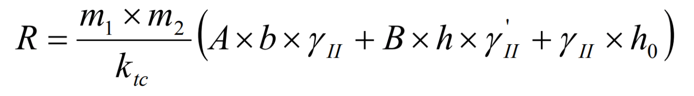
5.2. Interpretation of Parameters in the Formula
Each component in the formula above has a specific physical and technical meaning:
- m1 and m2: Working condition factors, considering elements like soil type and structure-foundation interaction characteristics.
- ktc: Reliability factor (or overall safety factor), typically taken as a minimum of 1.2.
- A, B, D: Dimensionless bearing capacity factors, primarily dependent on the design value of the soil’s internal friction angle, φII.
- b: The shorter side (width) of the foundation base.
- h: The depth of foundation embedment.
- γII: Design unit weights of the soil below and above the foundation level, respectively. (Note: Assuming gamma represents unit weight, adjust if context implies otherwise)
- cII: Design value of the soil’s cohesion.
5.3. Using the Annexes
The values of the bearing capacity factors A, B, and D are not calculated directly but must be looked up from tables in Annex E of the standard, based on the design friction angle φII.
The standard requiring users to look up critical factors from tables without providing the original analytical formulas is an inherited characteristic from the pre-computer era. This approach creates several problems in modern practice. Firstly, it requires manual interpolation when the friction angle falls between table values, leading to inaccuracies and inconsistency. Secondly, it complicates the automation of the calculation process using tools like spreadsheets or programming scripts. These tables are actually based on classic bearing capacity theories (e.g., by Terzaghi, Meyerhof, Vesic), and the original formulas can be readily programmed for precise calculation. Therefore, modern engineers should be aware of this limitation. A practical recommendation is to study the underlying theoretical formulas to build automated calculation tools, which enhances accuracy, efficiency, and transparency in the design process, overcoming the standard’s historical constraints.
Chapter 6: Calculation According to the Second Limit State (Deformation)
6.1. Core Principle: S ≤ Sgh
The fundamental and most important condition when checking SLS is: the calculated deformation of the foundation, S, must be less than or equal to the allowable limit deformation, Sgh.
6.2. Types of Deformation
The standard requires consideration of various types of deformation of the structure-foundation system, including:
- Absolute settlement (S): The vertical displacement of an individual footing.
- Average settlement (Stb): The average settlement value for the entire structure.
- Relative differential settlement (ΔS/L): The difference in settlement between two points on the foundation divided by the distance between them; this is the most critical parameter causing secondary stresses in the superstructure.
- Tilt (i): The difference in settlement between edge points of a footing or structure.
- Relative deflection or sag (f/L): Characterizes the bending of mat foundations or long strip footings.
6.3. Determining Allowable Limit Deformation Sgh
The allowable limit deformation Sgh is not a constant but depends on the type of structure, materials, and structural system. These values are specified in Table 16 of the standard. For example, a reinforced concrete frame structure will have a larger allowable differential settlement than a load-bearing masonry wall structure, which is very sensitive to uneven deformation.
6.4. Calculating Settlement (S)
Foundation settlement is calculated using the layer-wise summation method, detailed in Annex C of the standard. This procedure involves the main steps:
- Determine the zone of influence (compression zone) beneath the foundation base.
- Divide the compressible soil zone into thin layers.
- Calculate the increase in stress at the center of each soil layer caused by the foundation load.
- Calculate the settlement of each individual layer based on the stress increase and the layer’s deformation modulus.
- Sum the settlements of all layers within the zone of influence to obtain the total settlement at the foundation base.
Part III: Practical Design Process and Illustrative Example
This part translates theory into practice, providing a step-by-step guide and a detailed calculation example that engineers can reference.
Chapter 7: Step-by-Step Design Process
Below is a logical workflow for a typical shallow foundation design project according to TCVN 9362:2012.
- Data Collection: Gather architectural and structural drawings (to determine loads at column/wall bases) and the geotechnical investigation report (to determine soil stratigraphy and properties).
- Soil Profile Modeling: Simplify the soil stratigraphy from boreholes into a calculation model consisting of homogeneous soil layers. Determine design parameters from characteristic/standard values following guidance in Annex A.
- Preliminary Foundation Sizing: Use the design pressure R (calculated using the formula in Chapter 5) to make a preliminary estimate of the required foundation base area. This is just an initial step to get starting dimensions for the settlement check.
- Deformation Check (Primary Check): Perform a detailed settlement calculation S for the preliminary foundation size using the layer-wise summation method (Chapter 6).
- Adjustment and Optimization: Compare the calculated settlement S with the allowable limit settlement Sgh. If S > Sgh, increase the foundation dimensions and repeat step 4. This process is iterated until the condition S ≤ Sgh is satisfied.
- Bearing Capacity Check (If Required): If the project falls under the special cases mentioned in Chapter 4.4, perform the ULS check. Ensure the actual pressure under the foundation base is less than the design pressure R.
- Finalize Design: Finalize the foundation geometry and proceed to the reinforced concrete structural design phase for the foundation itself.
Chapter 8: Illustrative Example – Design of a Strip Footing Under a Wall
This section presents a specific numerical calculation example to illustrate the design process described.
8.1. Problem Statement
Design a reinforced concrete strip footing for a series of load-bearing walls in a 5-story residential building. Loads and geotechnical information are given in the table below.
Table 2: Illustrative Example – Input Parameters
[Note: The input parameter table from the original text should be inserted here. Assuming typical parameters:]
| Parameter | Value |
|---|---|
| Wall Load (Standard) Ntc | 250 kN/m |
| Foundation Depth h | 1.5 m |
| Soil Layer 1 (0-3m) | Clayey Sand, γII=18 kN/m³, φII=18°, cII=10 kPa, E0=8 MPa |
| Soil Layer 2 (>3m) | Stiff Clay, γII=19 kN/m³, φII=22°, cII=20 kPa, E0=15 MPa |
| Avg. Unit Weight above base γtb | 17 kN/m³ |
| Building Type | Residential, Load-bearing Walls |
8.2. Steps 1 & 2: Preliminary Sizing and Calculation of R
- Assume a preliminary footing width b = 1.2 m.
- Look up bearing capacity factors from Annex E for φII = 18°.
- Calculate the design pressure R using the formula in Chapter 5. Assume the calculated result is R ≈ 280 kPa.
- Check preliminary pressure: psb = Ntc / b = 250 / 1.2 ≈ 208 kPa.
- Since psb < R, the preliminary width b = 1.2 m is reasonable to proceed with the settlement check.
8.3. Step 3: Detailed Settlement Calculation (S)
Apply the layer-wise summation method according to Annex C.
- Calculate the net pressure causing settlement at the foundation base: pgl = pbase – γtb * h = (Ntc/b + γtb*h) – γtb*h = Ntc/b = 208 kPa.
- Divide the soil beneath the foundation into thin layers, e.g., each layer hi = 0.5 m thick.
- Calculate the stress increase σz at the center of each layer and the settlement of each layer Si = (σz,i / E0) * hi.
- Sum up Si to get the total settlement S.
Table 3: Illustrative Example – Settlement Calculation Table (SLS)
| Layer i | Depth z (m) | σz (kPa) | Si (mm) | Total S (mm) |
|---|---|---|---|---|
| 1 | 0.25 (below base) | ~195.5 | ~10.9 | 10.9 |
| 2 | 0.75 (below base) | ~156.0 | ~8.7 | 19.6 |
| 3 | 1.25 (below base) | ~118.6 | ~6.6 | 26.2 |
| 4 | 1.75 (below base) | ~89.4 | ~5.0 | 31.2 |
| … | … | … | … | … |
| Total Calculated | ~45 | |||
Note: The table above is illustrative; σz values need to be calculated accurately using stress distribution coefficients.
Assume the detailed calculation results in a total settlement S = 45mm (4.5 cm).
8.4. Step 4: Check Against Allowable Limit (Sgh)
- For a residential building with load-bearing walls, look up Table 16 of the standard. Assume the allowable absolute settlement limit is Sgh = 10 cm.
- Comparison: S = 4.5 cm ≤ Sgh = 10 cm.
- Conclusion: The deformation condition is satisfied. The footing width b = 1.2 m is acceptable.
Part IV: Advanced Topics and Special Soil Conditions
This section addresses specific guidance within the standard for complex soil conditions commonly encountered in Vietnam.
Chapter 9: Design Considerations for Problematic Soils
The standard dedicates a specific section to guide design on soils with special properties. For each type, engineers need to identify the risks and apply appropriate treatment measures.
9.1. Collapsible Soils
These are soils with high void ratios that can experience sudden volume reduction and significant settlement upon first wetting under load. The primary risk is unexpected wetting settlement (Ss). The standard requires identifying and calculating this settlement, and considering treatment measures such as deep compaction with heavy tamping, soil columns, or preventing water infiltration into the foundation soil.
9.2. Expansive Soils
These soils contain clay minerals that absorb water and increase in volume (swell) when wet, and shrink when dry. The risk is the heave or settlement of the foundation following moisture cycles, causing damage to the structure. Design solutions include embedding the foundation below the zone of stable moisture content, creating void spaces under foundation beams, or implementing moisture control measures around the structure.
9.3. Weak, Saturated Soils (Peat, Mud)
These soils are characterized by very low bearing capacity, high compressibility, and long-term consolidation settlement. Design on such soils requires careful checks for overall stability (ULS) and settlement prediction (both immediate and consolidation). Ground improvement techniques like vertical drains, preloading, sand compaction piles, etc., are often required.
9.4. Other Conditions
The standard also mentions other special soils like saline soils, fill materials, and design requirements for seismic zones, each with its own risks and specific treatment requirements.
Part V: In-depth Analysis and Future Perspectives
This final part provides expert-level analysis and critique, placing the standard in a broader context and offering valuable advice for practicing engineers.
Chapter 10: User Guide – A Critical Perspective for Practitioners
This section synthesizes expert analyses to offer practical advice.
10.1. Challenges from Complex Layout
Many experts and users have pointed out that the layout of TCVN 9362:2012 is quite complex and difficult to navigate. Provisions for a single calculation might be scattered across non-consecutive sections, requiring users to flip back and forth between chapters. For example, the conditions for checking bearing capacity are mentioned in both section 4.1.4 and section 4.7. To use it effectively, engineers should create their own lookup “roadmap” for common problems, noting the sequence of sections to reference for a more coherent design process.
10.2. Ambiguity and the Need for Interpretation
Some clauses in the standard can be interpreted in multiple ways. For example, the provision “foundations shall be calculated according to: a. the first limit state… b. the second limit state…” could be read as “and” (must calculate both) or “or” (calculate only one depending on the case), leading to different applications. In such cases, based on international practice and safety principles, engineers should lean towards the more conservative interpretation, i.e., checking all relevant conditions.
10.3. Overcoming Historical Limitations
As analyzed, the standard’s limitations, such as complex structure and reliance on lookup tables, are legacies of the past. Modern engineers should not be constrained by these. Proactively developing automated calculation tools (Excel spreadsheets, code snippets) based on the original theoretical formulas will increase speed, accuracy, and allow for sensitivity analyses easily, which manual calculations cannot achieve.
Chapter 11: TCVN 9362:2012 in the National and International Context
11.1. Comparison with TCVN 11823 (Bridge Design)
A notable comparative analysis reveals a very large difference in soil bearing capacity calculation results between TCVN 9362:2012 and TCVN 11823:2017 (bridge design standard). For the same soil type, the allowable bearing capacity calculated according to TCVN 9362:2012 can be 2 to 4 times greater than the result calculated according to the bridge standard.
This huge discrepancy indicates an inconsistency in the approach to safety and risk within Vietnam’s national standards system. The root cause lies in differing safety philosophies: TCVN 9362:2012 uses an overall safety factor ktc, while TCVN 11823 (based on the American AASHTO LRFD standard) uses the partial factor method, applying reduction factors to resistance (φb) and load factors. This implies that the acceptable risk level for a building foundation is specified more loosely than for a bridge foundation. This fragmentation suggests that different engineering fields (civil construction and transportation) have developed safety standards independently. This is an important context for engineers to recognize, especially in complex projects, and it raises questions about the need for future harmonization of standards.
11.2. Comparison with Eurocode 7
Eurocode 7 is the world’s leading geotechnical design standard system. Compared to TCVN 9362:2012, Eurocode 7 offers a more flexible and comprehensive design philosophy.
Table 4: Comparison of Main Design Approaches: TCVN 9362:2012 vs. Eurocode 7
[Note: The comparison table (Table 4) content from the original text should be inserted here. Assuming key comparison points:]
| Feature | TCVN 9362:2012 | Eurocode 7 |
|---|---|---|
| Limit States | ULS (Bearing Capacity) & SLS (Settlement) | ULS (EQU, STR, GEO, UPL, HYD) & SLS |
| Safety Approach | Overall Safety Factor (ktc) primarily for ULS | Partial Factor Method (Multiple Design Approaches DA1, DA2, DA3) |
| Bearing Capacity (ULS) | Single formula, factors from tables | Multiple formulas/methods allowed, partial factors applied to actions, material properties, or resistances |
| Settlement (SLS) | Layer-wise summation, check against limits in Table 16 | Various calculation methods allowed, check against project-specific requirements |
| Flexibility | Prescriptive, limited methods | More performance-based, allows various calculation models |
Chapter 12: Conclusion – The Future of Foundation Design Standards in Vietnam
TCVN 9362:2012 is a foundational standard, playing an indispensable role in the field of shallow foundation design in Vietnam. It provides a strict regulatory framework that has contributed to ensuring the safety of construction projects for decades. However, the analysis shows that this standard exhibits limitations due to its historical origins, manifested in a complex structure, reliance on traditional calculation methods, and inconsistencies with other national standards.
To use this standard effectively and safely, engineers need to equip themselves not only with knowledge of the formulas but also with a deep understanding of the context, potential limitations, and how to overcome them using modern tools and design thinking.
Looking ahead, reviewing and updating TCVN 9362:2012 is an urgent requirement. Future versions would greatly benefit from restructuring the layout for better logic and usability, harmonizing the safety philosophy with other specialized national standards, and gradually approaching the advanced design principles of international code suites such as Eurocode 7. This process will help enhance the quality, efficiency, and integration of Vietnam’s construction industry.
Design Standard for Foundations of Buildings and Structures
An interactive tool to explore TCVN 9362:2012. This standard specifies requirements for investigation, calculation, and design of foundations for civil and industrial construction projects. Understanding and correctly applying the standard is fundamental to the safety and sustainability of all structures.
Soil Classification and Geotechnical Properties
Soils are classified based on their physical and mechanical characteristics. Click on each soil type to view important geotechnical parameters specified in the standard.
Quick Calculation Tool
Apply formulas from the standard to quickly estimate the bearing capacity of the soil beneath a spread footing. This tool is for reference only and does not replace detailed design calculations by a qualified engineer.
Estimate Design Bearing Capacity (R)
Design Bearing Capacity (R):
– kPa
Formula (5.7) TCVN 9362:2012
R = m(A.b.γ + B.d.γ’ + D.c)
Limit States
Foundation design must be checked against two groups of limit states to ensure the structure is both safe regarding load-bearing capacity and stable during use.
Group I: Ultimate Limit States (ULS)
Calculations to ensure the foundation does not fail in strength or lose stability. This relates to bearing capacity, sliding stability, overturning, etc. The goal is to ensure the structure does not collapse.
Group II: Serviceability Limit States (SLS)
Calculations based on deformation to ensure normal operation of the structure. This relates to settlement, differential settlement, tilt, and other deformations not exceeding allowable limits, preventing structural cracking.
Standard Bearing Capacity (Rtc) Lookup
Chart visualizing standard bearing capacity (Rtc) values for some soil types according to Table G.1 (Annex G). Use the filter to view different soil groups.